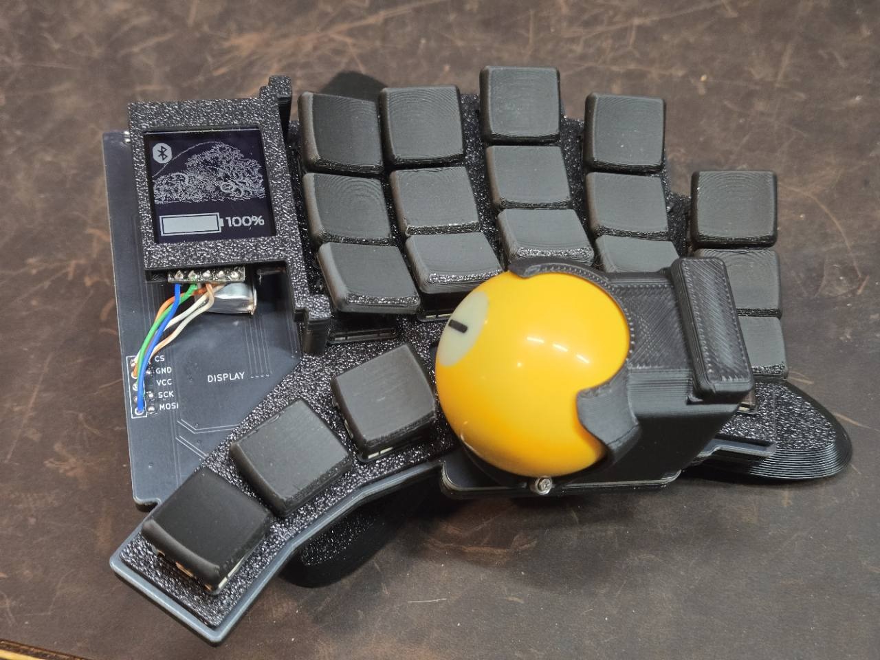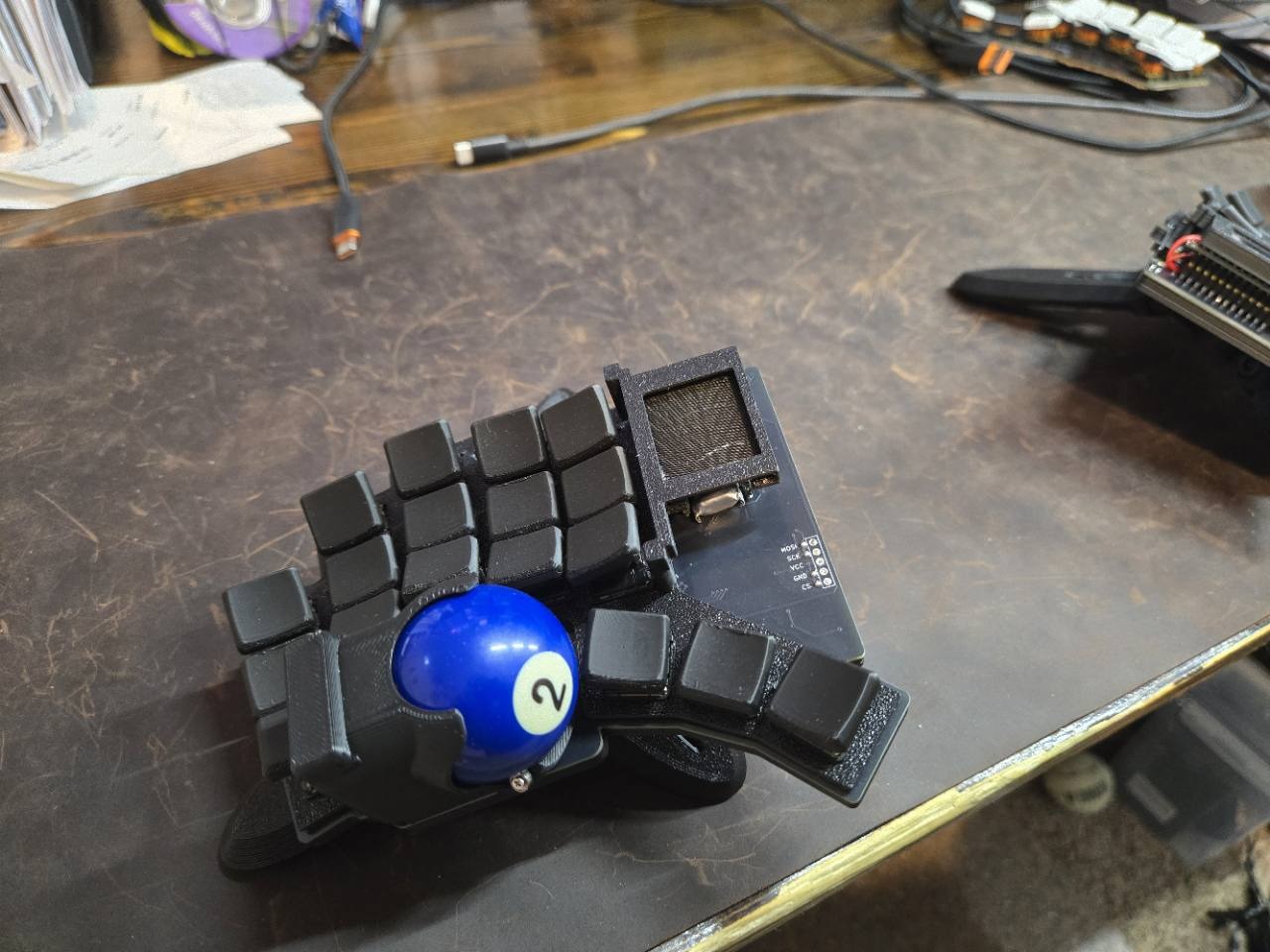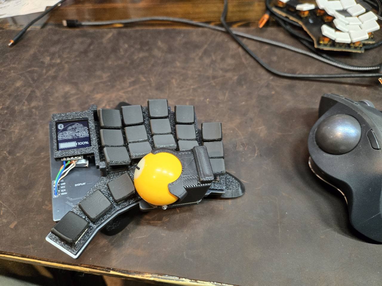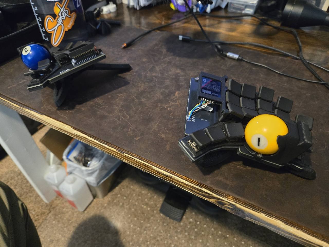
October update: The assembled keyboard now has both halves typing and both trackballs working. I still need to add the left display. This article includes what I learned getting to that point.
I wanted a low-profile split keyboard with trackballs built in, so I could type and move the pointer without reaching for a separate mouse. Tempest Dux is what I’ve been building to make that happen.
I did not start from a blank page, and I want to be clear about that. The ergonomics come from the dux family, Rae-Dux and Architeuthis Dux, and the PCB started from thrly’s Tempest. The firmware runs ZMK, with Manna Harbour’s Miryoku providing the keymap structure and Hands Down Gold as the alpha layer. The trackball driver is badjeff’s PMW3610 module. What I changed and built on top of that lineage is the part this log is about: my PCB modifications, the trackball integration, the plates and case, and the ZMK firmware that makes it one keyboard.
The PCB
I used Ergogen to define the key positions and generate the starting board, then moved into KiCad for routing and checks.
I also had to make room for the trackball hardware around the switches and the nice!nano v2 controller. The sensor, bearings, and printed holder all need space, and the current build has a trackball on each half.
Each switch has a diode and connects to a row and column in the keyboard matrix. I checked those connections, but I didn’t have a schematic for this version. I checked the Ergogen config and ran KiCad’s design-rule checks. There were still plenty of problems to find during assembly and troubleshooting.
Mechanical iteration
For the current build, I’m using 3D-printed plates in a layered stack with a TPU gasket. That’s assembled and screwed together now, but the trackball holders needed more work.
One version of the holder for the 38 mm pool balls fit pretty well, except the rear wall hit the outer bottom key switch. The right ball also brushed the innermost thumb key, so I clipped the corner off that keycap to give it more room.
For the next version, I want to sort out that clearance in the design so I can use an unmodified keycap. That means checking the fit with the actual switches and keycaps in place, including when the keys are pressed.
Firmware and bring-up
The keyboard runs ZMK, using Miryoku for the keymap structure and Hands Down Gold for the alpha layer. Getting it running took more than building and flashing the firmware. I also had to check what the controller was doing and whether its signals were actually reaching the display and trackball.
On the first prototype set, two display signals were present at the controller but weren’t reaching the display header. On the second set, the right trackball moved backwards on both axes and needed a different firmware build to match its sensor orientation.
Keeping track of which build belonged on which half became part of the job. For the next version, I want to simplify that so there’s one firmware build per side, with the pin mappings and hardware differences clearly documented.
What I would do differently
Making the board reversible added a lot of complexity for my first stab at designing/modifying a PCB. I had to keep track of multiple nets and how the connections changed depending on which jumpers were bridged. Then there were the display and trackball PCBs. Getting the connection order, routing, and orientation right was really difficult.
The Tempest PCB design was excellent, but I really barreled into this project and made major changes that ended up breaking a few things. I got it working, but it took hours of frustrating troubleshooting across many sessions, with several months-long breaks along the way.
I can’t tell you how many times I soldered diodes backwards or got the order of connections mixed up on the display and trackball headers. I even swapped the GND and VIN connections between one of the trackball PCBs and the Tempest Dux PCB. That was a potentially dangerous mistake. Things weren’t working on that side, and then I noticed the controller getting hot 😬.
It wasn’t as seamless and plug ‘n play as I was hoping, but I learned a ton! Now that I’ve gone through assembly and have both halves typing and tracking, I’m working on the next iteration. A few things I want to change:
- I’ll probably panelize the boards so each side is more or less mirrored but intentionally designed.
- Dedicated socket headers for the trackball and display.
- Clearer silkscreen labels and instructions!
I’m trying to focus on the process of creating a new thing: first make it exist, then make it work, then make it beautiful.
Earlier project history is on GitHub at samjolley/tempest_dux.